A plastic enclosure is a transparent window to electromagnetic radiation. Below roughly 30 MHz plastic is effectively invisible to the field; above it, the circuit inside radiates freely in both directions. For most consumer electronics that is manageable, but for anything that has to pass FCC Part 15, CE EMC Directive, or in-vehicle EMC testing to CISPR 25, EMI shielding is a design requirement, not an afterthought.
This article covers the shielding routes available to a moulded plastic enclosure, the attenuation each one delivers, and how to decide which fits your product. If you are at the earlier design stage of an enclosure, our existing consumer electronics enclosure design guide covers the geometric and DFM foundations — this piece picks up where that one ends.
How EMI shielding works
Shielding effectiveness (SE) is measured in decibels and describes how much the field strength is attenuated as it crosses the enclosure wall. A rough industry scale:
- Below 30 dB — minimal shielding, suitable for very low-emission products
- 30 to 60 dB — moderate shielding, covers most consumer and industrial EMC requirements
- 60 to 90 dB — high shielding, needed for sensitive instrumentation, medical, and defence
- Above 90 dB — specialised shielding, typically metal enclosures or Faraday cages
A bare injection moulded plastic enclosure delivers near-zero shielding. To get into the 30 to 60 dB range you need to add a conductive layer somewhere in the enclosure wall.
Route 1: Conductive coatings applied after moulding
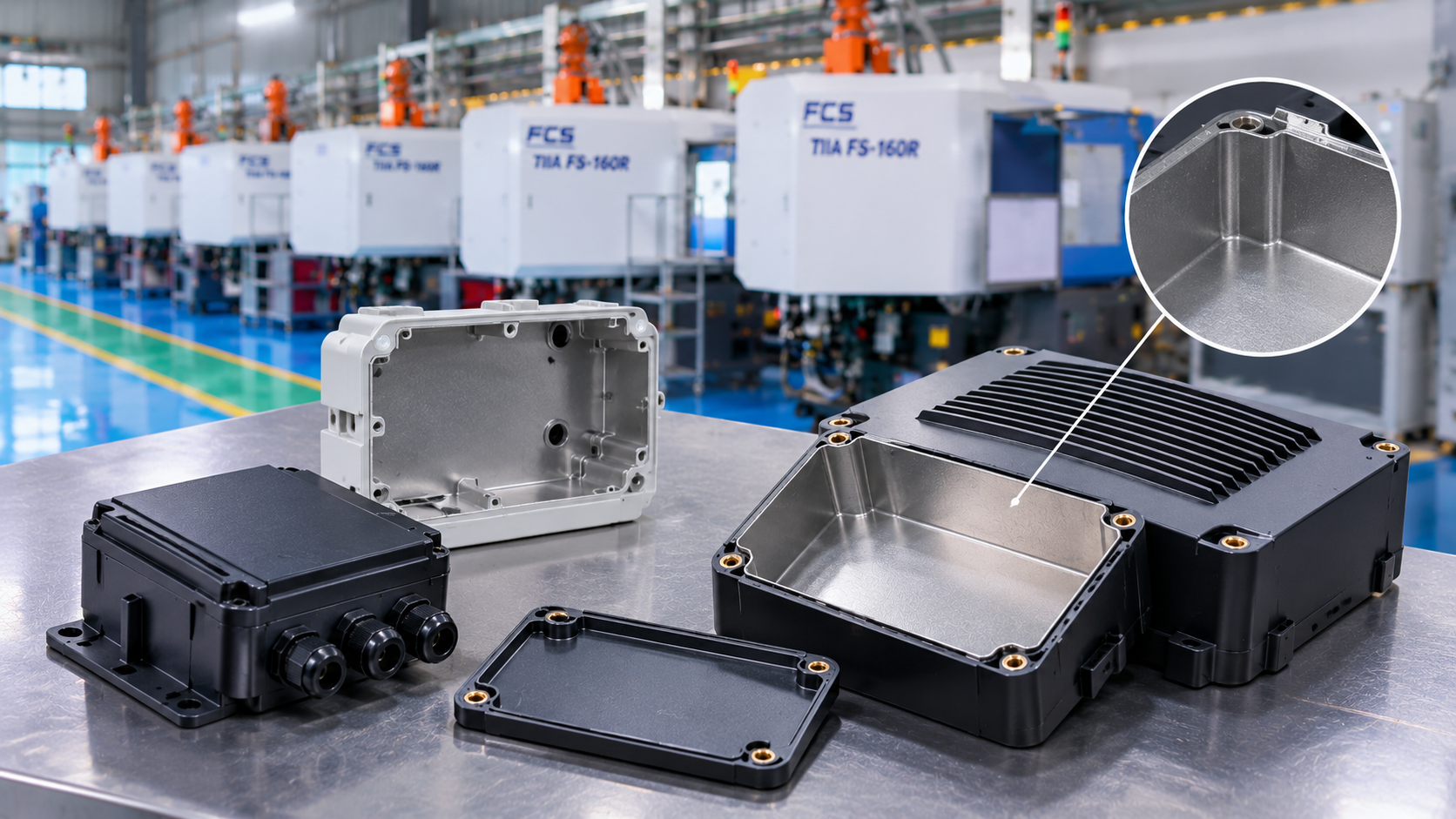
The most common approach. A plain plastic enclosure is moulded, then coated on the inside with a conductive layer. Four coating technologies dominate:
Conductive paint (silver, nickel, copper)
Sprayed onto the interior surface after masking. Silver-filled paints give the best SE (typically 60 to 80 dB in the 100 MHz to 1 GHz range) at the highest cost. Nickel and copper paints are more common for cost reasons, delivering 40 to 65 dB.
Trade-offs: adhesion depends on surface preparation; coating thickness variation leads to SE variation; paints can be scratched during assembly.
Electroless plating
A copper-nickel deposit grown chemically onto the plastic surface. Delivers 60 to 80 dB SE and better durability than paint. Requires an ABS or ABS-blend substrate for the standard plating process (etching relies on the butadiene phase).
Trade-offs: material choice is constrained; environmental handling of the plating line; higher cost than paint.
Vacuum metallisation (PVD)
Aluminium or silver vapour-deposited in a vacuum chamber. Thin coating (typically 1 to 3 microns), lower SE than plating (30 to 50 dB), but very uniform and cosmetically clean. Common in automotive interior trim with hidden-till-lit features where EMI is a secondary benefit.
Conductive adhesive foils
Pre-fabricated copper or aluminium foil with conductive adhesive, applied by hand or jig. Simple for low volumes and prototype shielding. Not a production solution for high volumes.
Route 2: Conductive plastic compounds
Instead of coating the enclosure, mould it from a plastic already loaded with a conductive filler. Three main compound types:
Carbon-filled compounds
Carbon black or carbon fibre added to a base resin (PA, PC, PP). SE in the 20 to 40 dB range — adequate for low-frequency and ESD applications, insufficient for high-frequency EMC. Low cost, easy to mould, but limited performance.
Stainless steel fibre compounds
Short stainless steel fibres compounded into the base resin at 5% to 10% loading. SE jumps to 50 to 70 dB. Suppliers include RTP Company and Lehvoss. Higher material cost but eliminates the secondary coating step.
Nickel-coated carbon fibre
Carbon fibres coated with a thin nickel layer, then compounded. Highest-performance filled compound, SE up to 75 dB, but material cost is substantial.
Trade-off for all filled compounds: cosmetic surface is compromised (fibres can show), mechanical properties shift (brittleness often increases), and tooling wear is higher. Our planned article on material comparison for engineering plastics covers related trade-offs with glass fibre.
Route 3: In-mould metal (hybrid shielding)
The enclosure is designed with a metal shielding insert — a stamped sheet metal cup, a woven mesh, or a formed foil — placed into the mould and overmoulded with plastic. This is a true insert moulding operation.
Advantages: SE equal to a bulk metal enclosure (80 to 100+ dB), one-piece assembly, no secondary coating line. Disadvantages: mould complexity, cycle time penalty for insert loading, and automation cost if volumes justify it.
Used in automotive radar housings, high-performance medical devices, and some high-end industrial sensors.
Gasketing and the enclosure seam
Shielding effectiveness is only as good as the enclosure's weakest seam. A 60 dB coating on the enclosure wall is worthless if the mating line between two halves leaks EMI. Seam shielding is handled with:
- Conductive elastomer gaskets — silver or nickel-filled silicone, compressed between the two halves
- Fingerstock gaskets — beryllium-copper fingers, high performance but higher cost
- Conductive foam gaskets — lower-cost option for moderate SE requirements
Gasket design is as important as material choice: compression force, groove geometry, and surface contact area all matter. The moulded groove needs to be dimensioned to the specific gasket cross-section with tolerances per the gasket supplier's datasheet.
Choosing the right route
Decision drivers in rough order of importance:
| Priority | Best route |
|---|---|
| Lowest unit cost at high volume, moderate SE (40-50 dB) | Conductive paint (nickel or copper) |
| Highest SE (60-80 dB) with good durability | Electroless plating on ABS |
| Clean cosmetic appearance, cost-sensitive | Vacuum metallisation |
| Low volume, simple geometry, no secondary line | Conductive compound (steel fibre) |
| Highest SE, structural integration | In-mould metal insert |
Standards and testing
The international reference methods for measuring shielding effectiveness:
- ASTM D4935 — Measuring the Electromagnetic Shielding Effectiveness of Planar Materials
- IEEE 299 — Measuring the Effectiveness of Electromagnetic Shielding Enclosures
- MIL-STD-285 — the older military shielding effectiveness test
For end-product EMC compliance, the applicable standards depend on market and application: FCC Part 15 for US consumer electronics, the CE EMC Directive and EN 55032/EN 55035 for Europe, CISPR 25 for in-vehicle equipment.
Choosing a moulder for shielded enclosures
A moulder qualifying for EMI-shielded enclosure work should offer:
- Experience moulding the target substrate (ABS for plating, PC/ABS for paint, PA for structural)
- In-house or qualified-partner coating line (paint, plating, PVD)
- Clean handling after coating to protect the shield layer
- Ability to validate gasket groove tolerances per the gasket spec
- If using filled compounds, hardened tooling to handle the abrasive filler
FD Group's FIFO Polymers division works with product teams through material selection, tooling design, and secondary coating partner coordination for EMI-shielded enclosures. If you are specifying a shielded enclosure for FCC, CE, or in-vehicle compliance, get in touch and we will help scope the right route.